Sevoflurane Liquid
Product Images NDC 10019-651

View Photos of Packaging, Regulatory Labels, and Product Appearance

Product Visual Gallery

This gallery contains 14 technical images submitted to the FDA as part of the official labeling for Sevoflurane (NDC 10019-651). Unlike standard consumer photos, these assets often include clinical data figures, molecular chemical structures, and official manufacturer packaging layouts.

As provided by Baxter Healthcare Company, these visuals offer a comprehensive scientific overview of the product's physical and chemical identity, aiding pharmacists and researchers in product verification and study.

FDA Label Image

Sevoflurane Structural Formula (Image 01)
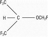
Sevoflurane Structural Formula (Image 01)
Chemical structure diagram of sevoflurane, showing the arrangement of carbon, hydrogen, oxygen, and fluorine atoms with trifluoromethyl groups and fluorinated ether moieties.*
FDA Label Image

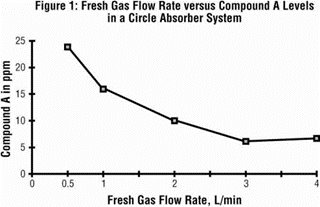
Figure 1 (Fresh Gas Flow Rate versus Compound A Levels in a Circle Absorber System)

Figure 1 (Fresh Gas Flow Rate versus Compound A Levels in a Circle Absorber System)
A line graph titled 'Fresh Gas Flow Rate versus Compound A Levels in a Circle Absorber System' depicting the relationship between fresh gas flow rate (L/min) on the x-axis and compound A concentration in ppm on the y-axis. The graph shows a decreasing trend in compound A levels as fresh gas flow rate increases from 0 to 4 L/min.*
FDA Label Image

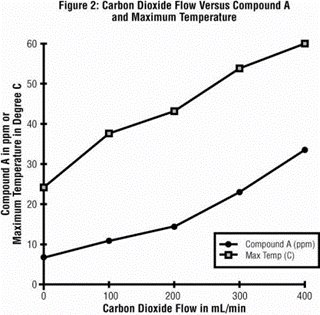
Figure 2 (Carbon Dioxide Flow Versus Compound A and Maximum Temperature)

Figure 2 (Carbon Dioxide Flow Versus Compound A and Maximum Temperature)
A line graph titled 'Carbon Dioxide Flow Versus Compound A and Maximum Temperature' showing the relationship between carbon dioxide flow in mL/min on the x-axis and compound A in ppm and maximum temperature in degrees Celsius on the y-axis. Two lines represent Compound A levels and maximum temperature, both increasing as carbon dioxide flow increases up to 400 mL/min.*
FDA Label Image

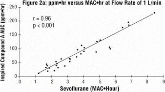
Figure 2a (ppm hr versus MAC hr at flow Rate of 1 L/min)

Figure 2a (ppm hr versus MAC hr at flow Rate of 1 L/min)
A scatter plot labeled Figure 2a showing the relationship between Sevoflurane exposure measured in MAC-hours on the x-axis and Inspired Compound A AUC (ppm·hr) on the y-axis, with a strong positive correlation (r = 0.96, p < 0.001) indicated by a fitted trend line through the data points.*
FDA Label Image

Figure 3. Ratio Of Concentration Of Anesthetic In Alveolar Gas To Inspired Gas (Image 05)

Figure 3. Ratio Of Concentration Of Anesthetic In Alveolar Gas To Inspired Gas (Image 05)
A line graph titled 'Ratio of Concentration of Anesthetic in Alveolar Gas to Inspired Gas' comparing the ratios over time (0 to 30 minutes) for five anesthetics: Halothane, Isoflurane, Sevoflurane, Desflurane, and N2O. The y-axis shows the ratio FA/FI (0 to 1), and the x-axis shows minutes of administration (0 to 30). Different symbols represent each anesthetic with N2O reaching near 1 fastest, followed by Desflurane, Sevoflurane, Isoflurane, and Halothane.*
FDA Label Image

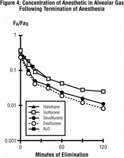
Figure 4 (Concentration of Anesthetic in Alveolar Gas Following Termination of Anesthesia)

Figure 4 (Concentration of Anesthetic in Alveolar Gas Following Termination of Anesthesia)
A line graph titled 'Concentration of Anesthetic in Alveolar Gas Following Termination of Anesthesia' showing the elimination of five anesthetic agents (Halothane, Isoflurane, Sevoflurane, Desflurane, N2O) over time (0 to 120 minutes). The y-axis depicts the ratio of anesthetic concentration (FA/FA0) on a logarithmic scale from 0.001 to 1. Different markers distinguish each agent, illustrating their decreases in concentration during elimination.*
FDA Label Image

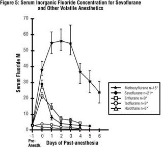
Figure 5 (Serum Inorganic Fluoride Concentration for Sevoflurane and Other Volatile Anesthetics)

Figure 5 (Serum Inorganic Fluoride Concentration for Sevoflurane and Other Volatile Anesthetics)
A line graph showing serum inorganic fluoride concentration over days post-anesthesia for several volatile anesthetics including Sevoflurane, Methoxyflurane, Enflurane, Isoflurane, and Halothane. The x-axis represents days post-anesthesia from pre-anesthesia to day 6, and the y-axis shows serum fluoride concentration in micromolar (M). Sevoflurane shows a peak in serum fluoride concentration around day 1 to 2, higher than other anesthetics.*
FDA Label Image

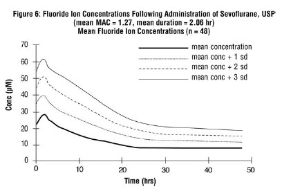
Figure 6 Fluoride Ion Concentration Following Administration Of Sevoflurane (Image 08)

Figure 6 Fluoride Ion Concentration Following Administration Of Sevoflurane (Image 08)
A line graph showing fluoride ion concentrations over time following administration of Sevoflurane, USP. The x-axis represents time in hours up to 50 hours, and the y-axis represents concentration in micromolar (µM) up to 70. Multiple lines illustrate mean concentration and mean plus standard deviations (±1, ±2, ±3 sd) for fluoride ion levels in a sample size of 48.*
FDA Label Image

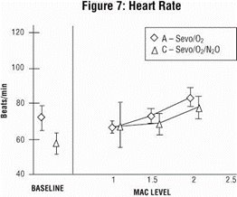
Figure 7 (Heart Rate)

Figure 7 (Heart Rate)
A line graph titled 'Figure 7: Heart Rate' displaying heart rate in beats per minute on the vertical axis and MAC level on the horizontal axis. The graph compares two groups labeled 'A – Sevo/O2' and 'C – Sevo/O2/N2O' using diamond and triangle markers, respectively, with error bars shown for each data point.*
FDA Label Image

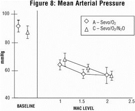
Figure 8 (Mean Arterial Pressure)

Figure 8 (Mean Arterial Pressure)
A line graph titled 'Mean Arterial Pressure' showing arterial pressure in mmHg across different MAC levels. Two data series are plotted: Sevoflurane with O2 (A) and Sevoflurane with O2/N2O (C), each with error bars indicating variability. The baseline pressure is shown on the left.*
FDA Label Image

Figure 9 (Systemic Vascular Resistance)

Figure 9 (Systemic Vascular Resistance)
A line graph titled 'Figure 9: Systemic Vascular Resistance' depicting the relationship between MAC level (x-axis, ranging from baseline to 2.5) and systemic vascular resistance (y-axis, in dyne·sec·cm⁻⁵, ranging approximately 400 to 1100). Two data series are compared: one labeled 'A – Sevo/O₂' represented by diamond markers and another labeled 'C – Sevo/O₂/N₂O' with triangle markers, both showing a decreasing trend in vascular resistance as MAC level increases.*
FDA Label Image

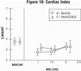
Figure 10 (Cardiac Index)

Figure 10 (Cardiac Index)
Figure 10: Cardiac Index graph showing cardiac index values (L/min/m²) plotted against MAC level. Two data series are represented: A - Sevo/O2 and C - Sevo/O2/N2O, with values ranging approximately from 2 to 5 L/min/m² across MAC levels from baseline to 2.5.*
FDA Label Image

Sevoflurane, Usp Representative Container Label (Image 13)

Sevoflurane, Usp Representative Container Label (Image 13)
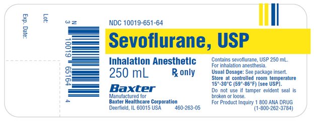
Sevoflurane USP 250 mL liquid inhalation anesthetic label from Baxter Healthcare Company. The label indicates prescription use, lot number, expiration date, and storage instructions at controlled room temperature. It also includes a barcode, manufacturer location in Deerfield, Illinois, and a product inquiry phone number.*
FDA Label Image

Sevoflurane, Usp Representative Carton Label (Image 14)

Sevoflurane, Usp Representative Carton Label (Image 14)
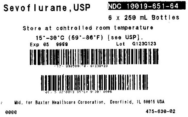
Sevoflurane USP NDC 10019-651-64 label for a pack of six 250 mL bottles. The label includes storage instructions to keep at controlled room temperature between 15-30°C (59-86°F). Manufactured for Baxter Healthcare Corporation, Deerfield, IL, USA. Barcodes and lot number Q1230123 visible.*

* About these descriptions: Image descriptions on this page are generated by automated AI analysis of the product label images from the manufacturer's FDA label submission (SPL). They are provided for reference only and may contain errors or omissions. Always rely on the printed label itself and the official FDA labeling, and consult a pharmacist or healthcare professional with any questions about this product.