Novolog Injection, Solution
Product Images NDC 50090-4500

65 FDA label images from A-s Medication Solutions · Packaging, Regulatory Labels, and Product Appearance

Product Visual Gallery

This gallery contains 65 technical images submitted to the FDA as part of the official labeling for Novolog (NDC 50090-4500). Unlike standard consumer photos, these assets often include clinical data figures, molecular chemical structures, and official manufacturer packaging layouts.

As provided by A-s Medication Solutions, these visuals offer a comprehensive scientific overview of the product's physical and chemical identity, aiding pharmacists and researchers in product verification and study.

Product Images & Figures Index

FDA Label Image

Fig. 1 (Structural Formula of Insulin Aspart)
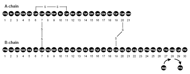
Fig. 1 (Structural Formula of Insulin Aspart)
Chemical structure diagram of insulin aspart showing its amino acid sequences for the A-chain and B-chain, with labeled cysteine residues connected by disulfide bonds, and a depiction of the substitution of proline by aspartic acid in the B-chain.*
FDA Label Image

Figure 2 (Image 02)

Figure 2 (Image 02)
A line graph showing serum glucose levels (mg/dL) over time (hours) from 0 to 6. The graph includes two lines: one solid and one dashed, representing different conditions or treatments affecting serum glucose concentration changes throughout the observed time interval.*
FDA Label Image

Fig. 3 (Pharmacodynamics Graph)

Fig. 3 (Pharmacodynamics Graph)
A line graph showing mean blood glucose levels (mg/dL) over time (minutes) before and after a designated reference point (R). The graph illustrates glucose values decreasing before R and then increasing afterwards, with error bars indicating variability. A note explains that slashes on the time axis represent a gap in recorded time intervals.*
FDA Label Image

Figure 4 (Image 04)

Figure 4 (Image 04)
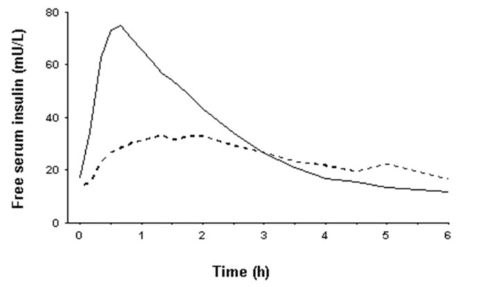
A graph showing free serum insulin concentration (mU/L) over time (hours). The chart compares two different insulin concentration curves, with one curve rising sharply to a peak around 0.5 hours before declining, and another curve with a more gradual increase and sustained levels over six hours.*
FDA Label Image

Vial Figure (Image 05)

Vial Figure (Image 05)
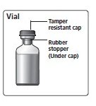
An illustration of a vial showing a tamper-resistant cap and a rubber stopper located under the cap.*
FDA Label Image

Hand And Vial Figure (Image 06)

Hand And Vial Figure (Image 06)
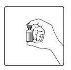
An illustration depicting a hand holding a small vial, likely representing the medication vial for injection. The image emphasizes proper handling or presentation of the vial, consistent with an injectable solution format.*
FDA Label Image

Figure A And Figure B (Image 07)

Figure A And Figure B (Image 07)
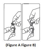
An instructional illustration showing two figures labeled A and B. Both depict a hand holding a vial with another hand removing or handling the vial's cap, demonstrating proper vial cap removal technique.*
FDA Label Image

Figure C (Image 08)

Figure C (Image 08)
An instructional illustration showing a hand holding a syringe above a vial, with an arrow indicating the syringe needle being inserted into the vial for withdrawal of liquid medication. An inset zooms in on the syringe barrel filled with liquid.*
FDA Label Image

Figure D (Image 09)

Figure D (Image 09)
An instructional illustration labeled Figure D showing hands using a syringe to withdraw liquid from a vial. The image depicts the proper technique for preparing an injection by drawing solution from the vial into the syringe.*
FDA Label Image

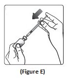
Figure E (Image 10)

Figure E (Image 10)
An instructional illustration labeled 'Figure E' showing a hand holding a syringe with an applied arrow indicating the plunger being pulled back, possibly depicting drawing medication into the syringe.*
FDA Label Image

Figure F (Image 11)

Figure F (Image 11)
An instructional illustration showing a hand holding a vial upside down with a syringe inserted into it, and an arrow indicating the direction of the syringe plunger being pulled to draw liquid from the vial. Labeled as Figure F.*
FDA Label Image

Figure G (Image 12)

Figure G (Image 12)
An instructional illustration labeled Figure G showing a person preparing an injection. The image depicts one hand holding a vial upside down and the other hand holding a syringe, drawing liquid from the vial into the syringe.*
FDA Label Image

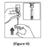
Figure H (Image 13)

Figure H (Image 13)
Illustration showing hands drawing insulin solution from a vial into a syringe. The vial is held upside down while the syringe plunger is being pulled to fill the syringe. A close-up inset shows the syringe with visible measurement markings.*
FDA Label Image

Figure I (Image 14)

Figure I (Image 14)
An instructional illustration showing a hand mounting or inserting a needle onto a syringe, with an arrow indicating the direction to push or twist the needle onto the syringe tip.*
FDA Label Image

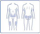
Fig. J (Image 15)

Fig. J (Image 15)
An instructional medical illustration showing front and back views of a human body. It highlights recommended injection sites with shaded areas on the abdomen, upper thighs, and upper buttocks. This illustration is typically used to guide subcutaneous injection locations.*
FDA Label Image

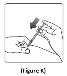
Figure K (Image 16)

Figure K (Image 16)
An instructional illustration showing two hands preparing an injection with a syringe. One hand holds the syringe and the other hand is positioning a cap or needle cover, indicated by a downward arrow above it.*
FDA Label Image

Figure L (Image 17)

Figure L (Image 17)
An instructional illustration showing a syringe injecting a solution into the upper thigh or arm of a patient. The syringe is held by a hand applying an upward motion indicated by an arrow, demonstrating how to properly administer an injection subcutaneously.*
FDA Label Image

Figure A Penfill Cartridge And Needle Components. (Image 18)

Figure A Penfill Cartridge And Needle Components. (Image 18)
Illustration showing components and assembly of NovoFine, NovoFine Plus, and NovoTwist pen needles including outer needle cap, inner needle cap, needle, and paper tab. It also depicts a PenFill cartridge compatible insulin delivery device, labeled with parts such as pen cap, cartridge holder, dose pointer, dose counter, dose selector/button, threaded end for needle attachment, colored band, and rubber plunger, demonstrating a 3 mL PenFill cartridge example.*
FDA Label Image

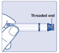
Figure B: Check The Penfill Cartridge. (Image 19)

Figure B: Check The Penfill Cartridge. (Image 19)
An instructional diagram showing a hand holding a syringe with a label pointing to the "threaded end" of the syringe tip. The illustration highlights the specific part of the syringe for connection.*
FDA Label Image

Figure C: Insert The Cartridge. (Image 20)

Figure C: Insert The Cartridge. (Image 20)
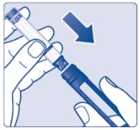
An instructional illustration showing hands attaching a needle or syringe to a pen injector device. The image uses blue and white colors and includes an arrow indicating the direction of connection for the injection assembly.*
FDA Label Image

Figure D: Pust The Needle Straight On. (Image 21)

Figure D: Pust The Needle Straight On. (Image 21)
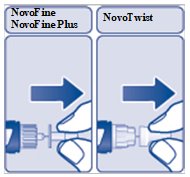
Illustration showing hand positions for using NovoFine, NovoFine Plus, and NovoTwist needle caps. The diagrams demonstrate how to properly grip and twist or pull the needle caps during injection preparation for insulin aspart injection solution.*
FDA Label Image

Figure E: Pull Off The Outer Needle Cap. (Image 22)

Figure E: Pull Off The Outer Needle Cap. (Image 22)
Illustration showing how to use the NovoTwist cap on a NovoFine or NovoFine Plus needle. The diagram indicates grasping the cap and twisting it off in the direction of the arrow to remove it.*
FDA Label Image

Figure F: Pull Off The Inner Needle Cap. (Image 23)

Figure F: Pull Off The Inner Needle Cap. (Image 23)
An instructional diagram showing how to connect a NovoFine or NovoFine Plus needle and a NovoTwist needle, each attached to an insulin injection pen. Arrows indicate the direction to attach or assemble the components for both needle types.*
FDA Label Image

Figure G: Insulin Squirts. (Image 24)

Figure G: Insulin Squirts. (Image 24)
NOVOLOG 100 units/mL injection solution vial with an attached curved needle, label partially visible. Product is intended for intravenous and subcutaneous use, labeled by A-S Medication Solutions. The image shows the vial capped and ready for use with the delivery needle.*
FDA Label Image

Figure H: Select Your Dose. (Image 25)

Figure H: Select Your Dose. (Image 25)
An instructional diagram illustrating the operation of a dose selector on a medical device. It shows a dose counter, dose selector, dose pointer, and an example dose of 12 units being selected by rotating the dose selector.*
FDA Label Image

Figure I: Injection Sites (Image 26)

Figure I: Injection Sites (Image 26)
An instructional diagram showing recommended injection sites for insulin administration. It highlights four areas on a human figure: upper arms, abdomen, upper thighs, and buttocks, with an inset zooming on the buttocks region.*
FDA Label Image

Figure J: Count Slowly. (Image 27)

Figure J: Count Slowly. (Image 27)
An instructional illustration showing a hand holding a NovoLog insulin injection pen against an arm, accompanied by a speech bubble instructing to count slowly from one to six. The image demonstrates how to properly administer the injection.*
FDA Label Image

Figure J: Lead The Needle Tip Into The Outer Cap. (Image 28)

Figure J: Lead The Needle Tip Into The Outer Cap. (Image 28)
An instructional diagram showing the connection of a syringe needle cap to the syringe of NOVOLOG (insulin aspart) injection solution. The image includes arrows indicating the direction to attach or detach the needle cap from the syringe barrel.*
FDA Label Image

Figure K: Unscrew The Needle. (Image 29)

Figure K: Unscrew The Needle. (Image 29)
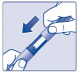
An instructional illustration showing a hand holding a cartridge holder with the other hand removing or twisting off a cap or cover from the top. A blue arrow indicates the direction to remove the cap. The illustration is labeled with "Cartridge holder."*
FDA Label Image

Figure L: Put The Cap On The Device. (Image 30)

Figure L: Put The Cap On The Device. (Image 30)
An illustration showing how to hold and press down on a pen-like injector device with one hand while positioning the other hand to receive an injection. A downward arrow indicates pressing the injector onto the skin.*
FDA Label Image

Figure A: Flextouch Pen And Needle Components. (Image 31)

Figure A: Flextouch Pen And Needle Components. (Image 31)
An instructional diagram showing components of three insulin needle types: NovoFine, NovoFine Plus, and NovoTwist, each with labels for outer needle cap, inner needle cap, needle, and paper tab. Also illustrated is a NovoLog FlexTouch insulin injection pen, with parts labeled including pen cap, insulin scale, insulin window, dose counter, dose selector, dose pointer, and dose button.*
FDA Label Image

Figure B (Image 32)

Figure B (Image 32)
An instructional illustration showing two hands holding an insulin vial, with one hand's thumb placing or removing an orange cap or seal from the vial's top, demonstrating how to prepare the vial for injection.*
FDA Label Image

Figure C (Image 33)

Figure C (Image 33)
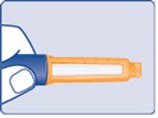
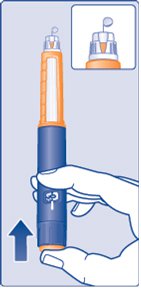
An illustration showing a close-up of a hand holding a blue and orange pen-type injection device, likely representing the administration method for an injectable solution such as insulin aspart.*
FDA Label Image

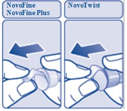
Figure D: Pull Off Paper Tab. (Image 34)

Figure D: Pull Off Paper Tab. (Image 34)
Instructional illustration comparing the use of NovoFine/NovoFine Plus and NovoTwist pen needles. The left panel shows a hand holding a small needle cap labeled NovoFine/NovoFine Plus with an arrow pointing left. The right panel shows a hand holding a needle cap labeled NovoTwist with an arrow pointing left, indicating how to remove or attach the needle cap.*
FDA Label Image

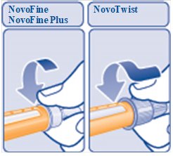
Figure E: Twist The Needle On. (Image 35)

Figure E: Twist The Needle On. (Image 35)
Instructional illustration showing two methods for attaching pen needles to an insulin pen: NovoFine/NovoFine Plus and NovoTwist. The first panel demonstrates connecting by pushing the needle onto the pen, while the second panel demonstrates twisting the needle onto the pen.*
FDA Label Image

Figure F: Pull Off Outer Needle Cap. (Image 36)

Figure F: Pull Off Outer Needle Cap. (Image 36)
An instructional illustration showing two methods for attaching needle components. The left panel demonstrates connecting a NovoFine or NovoFine Plus needle using a twisting or pushing motion, indicated by a rightward arrow. The right panel shows a NovoTwist needle being attached similarly with a rightward arrow. The images emphasize the correct way to assemble these insulin injection needles.*
FDA Label Image

Figure G: Pull Off The Inner Needle Cap. (Image 37)

Figure G: Pull Off The Inner Needle Cap. (Image 37)
Illustration showing instructions for attaching pen needles: on the left, attaching a NovoFine or NovoFine Plus needle by pushing onto the pen, and on the right, attaching a NovoTwist needle by twisting it onto the pen. Both images depict a close-up of hands handling pen needles for insulin injection devices.*
FDA Label Image

Figure H (Image 38)

Figure H (Image 38)
An instructional diagram showing a close-up of an insulin pen injector with a dial set to select 2 units of insulin aspart. The dial is being adjusted by a thumb, indicating dose selection for injection.*
FDA Label Image

Figure I (Image 39)

Figure I (Image 39)
An instructional illustration showing a hand holding an insulin pen injection device, applying gentle pressure to the top to administer the dose. The image suggests the operation of pressing the injection button on the pen.*
FDA Label Image

Figure J (Image 40)

Figure J (Image 40)
An instructional illustration showing a hand holding a NovoLog injection pen with the thumb pressing a button. An arrow below the pen indicates the direction to press upward. A smaller inset image shows a close-up of the pen's top section with a visible orange cap.*
FDA Label Image

Figure K (Image 41)

Figure K (Image 41)
Illustration showing a person adjusting a dosage selector on a pen injector for NOVOLOG (insulin aspart), Injection, Solution, 100 units/mL. The image demonstrates setting a dose of 5 units, with examples of 4-6 units and 24 units selected on the dial.*
FDA Label Image

Figure L (Image 42)

Figure L (Image 42)
An instructional illustration showing a close-up of a syringe with a visible liquid dose measurement scale marked up to 70 units. The syringe is partially filled, and the scale indicates an approximate dose. Blue text beside the syringe notes an example amount of approximately 200 units left in reference to the medication dose.*
FDA Label Image

Figure M (Image 43)

Figure M (Image 43)
Illustration showing front and back views of a female figure highlighting common injection sites on the upper arms, abdomen, and thighs, likely indicating areas for subcutaneous injection administration.*
FDA Label Image

Figure N (Image 44)

Figure N (Image 44)
Illustration showing a hand holding an insulin pen injection device upright, with a downward arrow indicating the direction to press or push the pen. The image likely demonstrates part of the injection preparation or administration process for a subcutaneous insulin injection.*
FDA Label Image

Figure O (Image 45)

Figure O (Image 45)
Illustration showing how to administer an injection with a syringe, depicting a hand holding the syringe and an arrow indicating the injection into the arm. The image includes a small icon of a syringe with the number 3, possibly indicating step 3 in a series of instructions.*
FDA Label Image

Figure P (Image 46)

Figure P (Image 46)
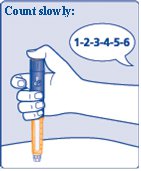
An instructional illustration showing a hand holding a pen-like injection device with the thumb on the top button and an orange window at the bottom. A speech bubble instructs to count slowly from 1 to 6, indicating how to administer or prepare the injection properly.*
FDA Label Image

Figure Q (Image 47)

Figure Q (Image 47)
An instructional illustration showing a syringe or pen-type injector positioned vertically with an upward-pointing arrow, indicating the direction or movement of the injection device tip. The image likely represents a step in the preparation or use of an injectable medication.*
FDA Label Image

Figure R: Remove The Needle. (Image 48)

Figure R: Remove The Needle. (Image 48)
An instructional diagram showing how to use the NovoFine and NovoFine Plus needles by twisting them off, and how to use the NovoTwist needle by pulling it straight off. The two parts are labeled accordingly with arrows indicating the removal direction.*
FDA Label Image

Figure S (Image 49)

Figure S (Image 49)
Instructional diagram showing how to connect a needle or syringe to a vial or injection pen for administration of a medication. The image includes directional arrows indicating the proper alignment and attachment process.*
FDA Label Image

Figure T (Image 50)

Figure T (Image 50)
An instructional illustration showing hands peeling a protective seal or cap from a device or vial. The image uses arrows to indicate the direction in which the seal is being removed, demonstrating how to open the packaging or prepare the device for use.*
FDA Label Image

Flextouch Qr Code Placeholder (Image 51)

FDA Label Image

Flextouch Cover (Image 52)

Flextouch Cover (Image 52)
Packaging label of NovoLog FlexTouch, an injection solution containing insulin aspart at 100 IU/mL. The label prominently features the NovoLog FlexTouch branding with instructions to 'Read before first use.' It includes the A-S Medication Solutions logo in the lower right corner.*
FDA Label Image

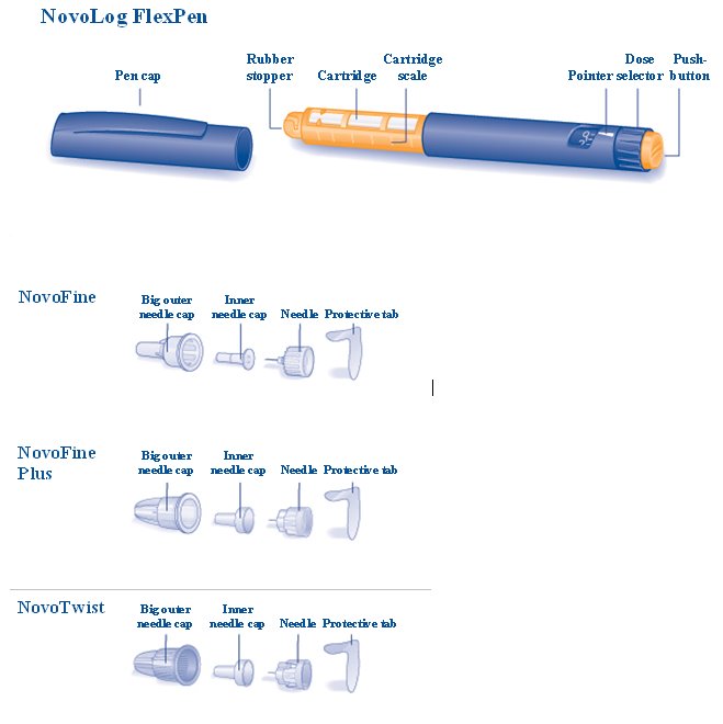
Flexpen And Needle Components. (Image 53)

Flexpen And Needle Components. (Image 53)
An illustrated diagram showing parts of the NovoLog FlexPen insulin injection device, including the pen cap, rubber stopper, cartridge, cartridge scale, dose selector, pointer, and push-button. The image also shows components of three needle types for the pen: NovoFine, NovoFine Plus, and NovoTwist, each with labeled parts: big outer needle cap, inner needle cap, needle, and protective tab.*
FDA Label Image

A (Preparing the NovoLog FlexPen)

A (Preparing the NovoLog FlexPen)
An instructional diagram showing a hand holding a Novolog insulin injection pen with the thumb pressing the injection button, demonstrating the method to administer the injection.*
FDA Label Image

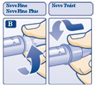
Diagram B: Attaching The Needle. (Image 55)

Diagram B: Attaching The Needle. (Image 55)
An instructional illustration labeled with "NovoFine" and "Novo Twist" showing a demonstration step where a cap is being removed from a needle attached to a syringe, indicating preparation for injection. The image highlights proper handling of the needle before use.*
FDA Label Image

Diagram C: Pull Off The Outer Needle Cap. (Image 56)

Diagram C: Pull Off The Outer Needle Cap. (Image 56)
An instructional illustration showing how to attach or twist a component on NovoFine or NovoFine Plus and NovoTwist injection devices. The image depicts hand positioning and arrow directions indicating the twisting motion for proper assembly or use.*
FDA Label Image

Diagram D: Pull Off Inner Needle Cap. (Image 57)

Diagram D: Pull Off Inner Needle Cap. (Image 57)
An instructional illustration showing proper technique for preparing NovoFine and NovoFine Plus needles (left panel) and NovoTwist needles (right panel) for use with NOVOLOG insulin aspart injection. Each panel depicts hands handling the respective needle types to demonstrate correct assembly or attachment steps.*
FDA Label Image

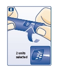
E (Giving the airshot before each injection- Turn the dose selector to select 2 units)

E (Giving the airshot before each injection- Turn the dose selector to select 2 units)
An instructional illustration showing the adjustment of a dosing dial on a pen-style injector for insulin aspart injection. The image highlights selecting 2 units on the dosage window, indicating dose setting for subcutaneous injection.*
FDA Label Image

F (Giving the airshot before each injection)

F (Giving the airshot before each injection)
An instructional illustration showing a hand flicking the top of a syringe containing a liquid solution, with motion lines indicating the flicking action. The syringe appears to be prepared for injection.*
FDA Label Image

G (Giving the airshot before each injection)

G (Giving the airshot before each injection)
An instructional illustration showing a hand holding a pen-like device with a cap being pulled upward, likely indicating how to prepare or prime a pen injector. A smaller inset image zooms in on the needle tip of the device, emphasizing the area where the cap is removed.*
FDA Label Image

H (Selecting the dose)

H (Selecting the dose)
An instructional illustration depicting the dose selector on a NOVOLOG insulin aspart injection pen. The image shows a hand adjusting the dial to select doses of 5 units and 24 units as examples, with close-ups highlighting the numbers on the dose selector.*
FDA Label Image

I (Giving the injection)

I (Giving the injection)
An instructional illustration showing a person removing a protective cap from a vial. The image highlights the downward motion of the thumb pressing on the cap, intended to demonstrate how to open the vial properly before use.*
FDA Label Image

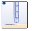
J (Giving the injection)

J (Giving the injection)
An instructional illustration showing a close-up of an injection pen or syringe needle positioned above skin, demonstrating preparation for an injection.*
FDA Label Image

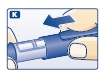
K (After the injection)

K (After the injection)
An instructional illustration showing a close-up of a person's fingers gripping the end of a syringe or pen device. A blue arrow points to the right, indicating a twisting or turning motion, likely part of preparing or using the injection device.*
FDA Label Image

Label Image (Lbl500904500)

Label Image (Lbl500904500)
NOVOLOG 100 Units/mL Insulin Aspart Injection 5 x 3 mL Prefilled Syringes carton label from A-S Medication Solutions. The label indicates it is a sterile solution for intravenous and subcutaneous use. Each mL contains 100 units of insulin aspart.*

* About these descriptions: Image descriptions on this page are generated by automated AI analysis of the product label images from the manufacturer's FDA label submission (SPL). They are provided for reference only and may contain errors or omissions. Always rely on the printed label itself and the official FDA labeling, and consult a pharmacist or healthcare professional with any questions about this product.